junmar, Author at Comnet - Page 2 of 2

What is the difference between OM3, OM4, OM5 Multimode Fiber

What is the difference between OM3, OM4, OM5 Multimode Fiber

We understand all the advantages we can get from using Fiber Optics as means for data transmission such as low attenuation, infinite bandwidth, and non EMI/RFI … etc.

For Long Distance (Kilometers) we choose for Singlemode Fibers and using Lasers as transmitter whereas for building networks (meters) we go for Multimode Fibers that uses VCSEL transmitter.

Multimode optical fiber accepts many modes of light because it has a large numerical aperture.  It supports wavelength of 850nm and 1300nm.

Singlemode optical fiber accepts only the axial mode of light for propagation and it has small core diameter of about 7 to 9 micron.  There is no modal dispersion and hence this provides the largest bandwidth and ability to go the longest distance.

OM3, OM4 and OM5 are all laser optimized multimode fiber.

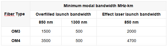
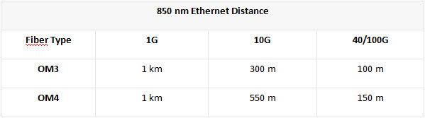
OM3 fiber was introduced way back in 1999 and it supports 300 meters for 10 Gb/s Ethernet. OM3 fiber with and effective modal bandwidth of 2000MHz/Km

OM4 fiber can support 550 meters for 10 Gb/s Ethernet with effective modal bandwidth of 4700MHz/Km

For 100 Gb/s Ethernet, OM3 can support 100 meters while OM4 is 125 meters.

WHY OM5?

OM5 is also known as WBMMF –  Wideband multimode fiber.

This means that OM5 can support WDM whereas OM3 and OM4 are for supporting only 1 wavelength at 850nm.

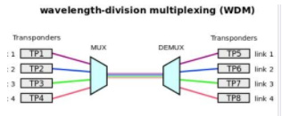
WDM is short for wavelength-division multiplexing.  WDM is technology which multiplexes a number of optical carrier signals onto a single optical fiber by using different wavelengths of laser light.  This enables 4 different transceivers to be multiplex into single fiber for Tx and another fiber for Rx.

Next generations Terabit Ethernet (TbE)  200 and 400 Gigabit Ethernet uses WDM for multimode fiber and may use OM5 which has a band of 850nm to 953nm for the wavelength of transmitters.

Here is a look at WDM:

WDM had been applied extensively in singlemode fiber optics cables.

Basic (BWDM), Coarse (CWDM) and Dense (DWDM) are different methods employed for singlemode fiber optical systems.

BWDM uses 1310nm and 1550nm on 1 fiber.

CWDM provides 16 channels over 1530nm to 1565nm while DWDM can provide 40 channels using 100Ghz spacing or 80 channels using 50 GHz spacing.

WDM can be applied in Multimode fiber optics cables which can support 4 channels using 30nm wavelength spacing from 850nm to 953nm.

This is the new OM5 specified Multimode fiber optics cables,

OM5 Multimode fiber optics cables can support multiple ‘short’ wavelengths of between 850nm and 953nm that can be aggregated for higher bandwidth applications.  For 4 wavelength of light that can transmit 25Gps will results in 100Gps in a single fiber. Using a pair of fiber for DUPLEX therefore will allow the 100Gps transmission using only 2 fibers compared with 20 fibers via the 10Gbps X 10 lanes also known as Parallel Optics.

OM3 and OM4 is primarily designed to support a single wavelength of 850nm.

OM5 also has core of 50um and cladding of 125um which is the same as OM3 and OM4 and hence are backward compatible to these fibers.

For any applications / Systems operating at a single 850nm wavelength OM5 fiber provides no greater bandwidth than OM4.

What is Structured Cabling?

What is Structured Cabling?

Structured Cabling is a broad term for the linking of network devices in a system that consists of cabling and associated hardware, forming a comprehensive telecommunications infrastructure.

According to the Fiber Optic Association, “structured cabling is the standardized architecture and components for communications cabling specified by the EIA/TIA TR42 committee and used as a voluntary standard by manufacturers to ensure interoperability.

If well designed and installed by professionals, it will provide an infrastructure that ensures predictable performance as well as the ability to accommodate Moves, Additions and Changes (MAC) flexibly.

WHAT IS IT USED FOR?

Structured Cabling is a data transmission system that supports the transmission of data through a computer network, multiple voices, video, telephone services and other management systems such as security access and energy systems. Network Cabling is not device-dependent, so it serves a wide range of uses.

Every structured cabling system is unique to the company or organization. This is due to a few factors:

  • Architectural Structure of the building that houses the cabling system
  • Type of cable and connection products
  • Function of cabling installation
  • Type of equipment the cabling installation supports
  • Configuration of the current system
  • Customer Requirements
  • Manufacturer Warranties

While every structured cabling setup is unique and different for various purposes, there is a standardised method to complete and maintain cabling installations.

WHAT ARE THE SIX SUBSYSTEMS OF A STRUCTURED CABLING SYSTEM

There are the main components of building a structured cabling system, and it consists of six subsystems:

1. ENTRANCE FACILITY

This contains cables, network demarcation point(s) connecting hardware, protection devices and other equipment connecting to the access provider (AP) or private network cabling. This  includes connections between the outside plant and the cabling inside the building.

2. EQUIPMENT ROOM

This houses the centralised space for telecommunication equipment which is environmentally controlled, which is the house equipment and wiring consolidation points. This serves users inside the building or campus.

3. TELECOMMUNICATIONS ROOM OR ENCLOSURE

This is an enclosed area designed  to house telecommunications equipment, cable terminations, cross-connects and distribution frames. In general, each building will have at least one telecommunications room or enclosure. The size of the room is dependent on the size of the service area.

4. BACKBONE CABLING

Also known as vertical cabling or wiring, it offers interconnection between entrance facilities, telecommunication rooms and equipment rooms. This is commonly done from floor to floor or between buildings. Equipment is to be connected by cables not longer than 30m. The cables can be fibre optic, coaxial, unshielded twisted-pair (UTP), and shielded twisted-pair (STP).

5. HORIZONTAL CABLING

Horizontal cabling is the cabling between telecommunications information outlet in the work area and horizontal cross-connect in the telecommunication room(TR) or telecommunications enclosure(TE). This contains the telecommunications outlet, optional consolidation points, horizontal cable, mechanical terminations, patch cords or jumpers located in the TR or TE. It will usually run above the ceiling or below the floor. Ethernet or fibre optic cables are usually used for horizontal cabling.

6. WORK AREA

Components in the Work Area(WA) extend from the telecommunications outlet/connector end of the horizontal cabling system to the WA equipment, connecting to end-user equipment. WA components are also known as cable components, including patch cables, communication outlets and station equipment.

WHAT ARE THE BENEFITS?

The benefits of using structured network cabling are:

  • Cost-Effective
  • Reduces the risk of downtime since it is organised, keeping errors and issues easy to identify
  • Time-Saving, as Structural Cabling is flexible to accommodate Moves, Additions and Changes (MAC) quickly.
  • Consistency of design and installation
  • Uniform documentation, easy for people who are new to understand how it runs.
  • Supplies higher bandwidth
  • All-in-one communication system that is streamlined for easy management
  • Reduce cost by unified all cable support systems into one


Structured Cabling is the recommended system for companies and organizations looking for an organised and standardized system for their cabling needs. It is important to choose the right kind of cabling system that fits the requirement of your project best, as it can have an impact on its functionality and cost of ownership. There are network cabling companies that provide structured cabling services that can serve your needs, however it is important to look for companies with the track records and industry certifications so as you can tap on their expertise and experience immediately for your project.


Choosing Between OM3 and OM4 Fiber Optics Cables

Choosing Between OM3 and OM4 Fiber Optics Cables

Overview

The OM3 and OM4 fibers are laser-optimized with a 50/125 core, which is made to comply with the ISO 11801 Standard. The OM3 fiber specs indicate that the OM3 is particularly made for 10 Gb/s transmission speed, but it is also compatible with, and can function under 40 Gb/s and 100 Gb/s. The OM4 fiber is the improved version of the OM3 fiber. The OM4 fiber is mainly used for an Ethernet of 10G, 40G, and 100G. The OM3 and OM4 fiber optics have a minimum of 2000 MHz*km EMB (Effective Modal Bandwidth or laser bandwidth) and 4700 MHz*km EMB respectively. This means that the OM3 can move 2000 Megahertz of data up to 1 km, and OM4 can move 4700 Megahertz of data up to 1 km. For both OM3 and OM4 cables, the EMB is the most effective when the distance remains at 1 km or under; a distance of over 1 km would slow down transmission speed. Regarding compatibility, the OM4 is entirely backwards compatible with the OM3 fiber optics. The chart below provides detailed information on the minimum modal bandwidths of the OM3 and OM4 fibers.

Distance and Speed

The OM3 and OM4 multimode fibers are compatible with 1GbE, 10GbE, 40GbE, and 100GbE applications, but their transmission distance depends on the application. The chart below displays the maximum transmission distances of the OM3 and OM4 fibers under different transmission speeds. Referring to a speed of 10 Gb/s as an example, with a distance of 550m, the OM4 fiber projects over a longer distance than the OM3 fiber, which only projects a distance of 330m.

However, through the usage of parallel-optics transmission technology, 40G and 100G Ethernet can transmit and receive data simultaneously over multiple fiber optics. The 40G interfaces are 4x10G channels on four fibers per direction, then the OM3/OM4 cable terminated with an 8/12 fiber MTP/MPO connector can be used for 40 Gb/s transmission. 100G interfaces are 10x10G channels on 10 fibers per direction, then the OM3/OM4 cable terminated with the 24 fiber MTP/MPO connector is supposed to support 100 Gb/s.

Price Difference

The OM4 fiber cable costs a third more than the OM3 cable. To a large extent, cost also depends on the construction type of the cable (loose tube, tight buffered, etc.). The cost differences for the fiber accessories such as fiber patch panels, MTP cassette modules, and fiber patch cords, however, are minimal.

Choosing Between OM3 or OM4 Fiber

To decide whether to choose the OM3 or OM4 fiber, you have two considerations to make. One being the distance limitations of your existing multimode network application. If it exceeds the distance of the OM3 fiber, then the OM4 fiber would be the natural choice. Secondly, you would also have to consider whether you would be upgrading to a higher network speed during the lifespan of the fiber optic cable plant. If you will be, the OM4 fiber would be able to provide you with higher data rates transmission at a longer distance.

ELV Cabling Solution

ELV Cabling Solution

As an ELV Cabling Specialist with BCA ME04 L5 Work-head, besides data system, we integrate all your other ELV systems and services to operate seamlessly on a single cable plant, examples of such services are

  • VoIP telephony system
  • CCTV surveillance system
  • Traffic counting system
  • Security Control and Access system
  • PA system
  • Car-park System
  • Digital video /sign board/whiteboard
  • IPTV System
  • AV IT System
  • Power Management System
  • Building Management System
  • Other ELV systems

We provide complete services for cabling & network ELV infrastructure from

  • Design
  • Installation
  • Testing & Commission
  • Maintenance & Enhancement

We are experienced in not only integrating the cabling system for different ELV systems but also designing and implementing network infrastructure to connect all the different ELV systems together


HOW TO SELECT AN ELV CABLING SPECIALIST

  • Does the ELV Cabling Specialist have the relevant experience on the size of the project or the relevant BCA work-head to do the project?
  • Does the ELV Cabling Specialist have relevant experience on integrating different ELV systems together?
  • Does the ELV Cabling Specialist have relevant experience on integrating the network systems for different ELV systems together?
  • Does the ELV Cabling Specialist have certified cabling and network engineer to execute the project?


CHALLENGES WHEN INTEGRATING DIFFERENT ELV SYSTEMS

  • Do you need to integrate with existing ELV systems?
  • Any distance limitation for ELV devices?
  • Any outdoor requirement for ELV devices?
  • Separate network system or integrated network system for all the different ELV Systems?
  • Do you need to customise the enclosure inside the ELV riser?
  • Is network IP routing required for different IP address range for the different ELV systems?